
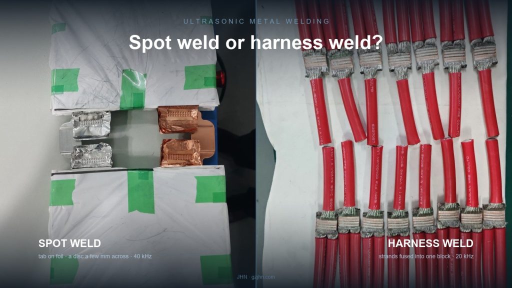
A battery tab and a 50 mm² harness splice are both “ultrasonic metal welding”. They are not the same job, and the machines are not interchangeable.
We get the same question about twice a month: someone has a wire harness welder and wants to weld battery tabs with it, or the reverse. Usually the machine can be made to fire. The joint that comes out is where the trouble starts.
The two processes differ in what the horn presses against, how much energy has to arrive in that area, and what a good joint looks like afterwards. Sort those three out and the choice stops being a matter of preference.
The difference is the shape of the joint, not the size of the machine
A spot weld joins two surfaces that lie flat against each other. The horn comes down on one point, energy is concentrated there, and the bond forms in a disc a few millimetres across. Think of a nickel tab on a copper foil stack, or a terminal flag folded over a wire end.
A harness weld joins the end face of a bundle. The strands are gathered, the horn presses the whole end against an anvil, and the weld is the full cross-section of the bundle squeezed into a solid block. Nothing is “spotted” — the entire end becomes one piece of metal.
That difference drives everything downstream:
| Spot welding | Harness / terminal welding | |
|---|---|---|
| Contact area | a point, a few mm across | the full end face of the bundle |
| What you see afterwards | a shallow disc imprint | the strands fused into one block, often visibly flattened |
| Typical stack | thin foil on foil, tab on busbar | many strands, or wire into a terminal |
| Frequency used | often 40 kHz | mostly 20 kHz |
| Machine class | 1.5 – 2 kW | 3 – 12 kW |
| Failure if mismatched | burn-through, pierced foil | false weld: holds on the outside, unbonded inside |
Two rows in that table explain most of the disappointment we hear about. Spot welding runs higher frequency because thin foil cannot absorb a big 20 kHz stroke without tearing. Harness welding runs more power because the energy has to reach through a much larger volume of copper.
Spot welding: when it is the right answer
Spot welding is correct when the joint is a lap between two thin things, and the heat-affected zone has to stay small.
Typical cases:
- Battery tabs. Nickel tab to copper foil, tab to busbar, positive and negative electrode stacks. The foil is often 6–20 µm; a low-amplitude 40 kHz stroke bonds it without punching through.
- Terminal flags and small lugs. A folded terminal over a small wire end, where the weld is a localised spot rather than the whole section.
- Sensor leads and fine wire. Anything where the metal around the joint cannot take a full-section squeeze.
On our own line this is the 40 kHz family: the JHN-4015 at 1.5 kW and the JHN-4016-A at 1.6 kW, plus the half-wave and full-wave battery tab welders (JHN-4008, JHN-3570) for stacks that need a specific electrode polarity.
The limit is thickness, and it is a hard limit. Once you are welding solid copper above roughly 1 mm, a 1.5 kW spot machine runs out of energy before it runs out of travel — you get a mark, not a weld.
Harness welding: when it is the right answer
Harness welding is correct when the job is to turn many strands into one conductor, replacing a crimp or a solder joint.
Typical cases:
- Splice joints. Two or more wires joined mid-run. The alternative is a crimp sleeve, which adds resistance, mass and a corrosion path.
- Wire into terminal. The wire end is welded into the terminal barrel instead of crimped. Common where vibration or thermal cycling kills crimps.
- Large cross-sections. 20, 50, 70 mm². This is where ultrasonic starts to beat crimping on both resistance and pull force.
The machine class spans an order of magnitude because the cross-section does. Our range runs from the JHN-2030 at 3 kW (0.5–20 mm²) through the JHN-2060 at 6 kW to the JHN-2012G at 12 kW and the JHN-2080 at 8 kW. Terminal work sits in the same family: the JHN-2056 handles up to 50 mm², the JHN-2080-T and JHN-2012G-A cover heavier terminal welds.
Note what the power numbers do *not* tell you. A 12 kW machine is not “better” than a 3 kW one. It has a bigger transformer and a bigger horn, which lets it deliver energy into a larger area. Put a 12 kW horn on a 1 mm² wire and you will destroy it faster than a 3 kW machine would.
The decision table
Work down this list before looking at a catalogue.
| Joint | Material | Cross-section / thickness | Process | Watch out for |
|---|---|---|---|---|
| Battery tab to foil | Ni–Cu, Cu–Al | foil 6–20 µm | spot, 40 kHz, 1.5–2 kW | amplitude too high pierces the foil |
| Tab to busbar | Cu–Cu, Al–Al | tab 0.2–0.5 mm | spot, 20–40 kHz | anvil flatness; a worn anvil shows as a crescent imprint |
| Wire splice, mid-run | Cu–Cu | 0.5–20 mm² | harness, 3–6 kW | strand spread before welding; loose strands never bond |
| Wire into terminal | Cu–Cu, Cu–Al | 10–50 mm² | terminal, 6–12 kW | terminal wall thickness vs horn footprint |
| Busbar / foil stack | Cu, Al | stack 20+ layers | harness or full-wave | layer count sets the energy; do not scale linearly |
| Copper to aluminium | Cu–Al | any | either, with process control | intermetallic growth — see the amplitude data below |
The last row deserves a warning. Cu–Al is not “the same job with a different metal”. The window where you get a bond without excessive intermetallic formation is narrow, and it has to be found per cross-section. We published the measured window for 70 mm² Cu–Al splices separately, because a table of current settings would be useless to anyone with a different stack.
Three mismatches we see repeatedly
1. A harness welder used on battery tabs. The machine has the energy, so it fires. The foil under the horn is pierced rather than bonded, and the scrap rate only shows up at end-of-line electrical test. The fix is not a setting — it is a different machine class.
2. A spot welder used on 50 mm². This one is worse, because it *looks* like it worked. The outer strands fuse, the joint feels solid, and a pull test can pass. Cut it open and the centre is still loose strand. The pull force was carried by the outer layer only.
If you cannot cut samples, this is the failure mode that will reach your customer.
3. Buying by power instead of by horn. The horn and anvil geometry decide how the force and the energy arrive at the joint. A 6 kW machine with the wrong horn footprint will underperform a 3 kW machine with the right one. Ask what the horn face area is before asking what the power is.
Power is a range, not a number
Every ultrasonic metal weld sits inside a window bounded by three settings: amplitude, pressure and weld time. Move outside it in any direction and the joint degrades — cold weld on one side, over-weld and cracking on the other.
This is why two plants with “the same” 6 kW machine get different results on the same wire. The machine is the same; the window they landed in is not.
When we commission a machine we record the amplitude at the horn face, the resonant frequency and impedance of the new stack, and the appearance of an unworn face. Those numbers only exist on day one. Six months later, every comparison you make without them is a guess.
Telling a good joint from a bad one
The inspection method should match the process, because the two fail differently.
By eye. A spot weld leaves a shallow disc imprint, roughly the shape of the horn tip, with the foil underneath intact. If you can see a ring of pierced foil around the imprint, the amplitude was too high. A harness weld comes out visibly flattened, slightly wider at the middle than the ends. If the strands still read as separate lines on the surface, the weld did not reach the centre.
By cross-section. Cut across the joint, polish, and look at the boundary. A real weld has no line where the two parts met — the grains are continuous. A false weld shows a straight, sharp boundary that looks like two clean surfaces pressed together. This is the only check that catches the 50 mm² failure described above; a pull test will not.
By pull test. Useful, but read it carefully. A pull value above the wire’s own breaking load tells you the joint is not the weak point. It does not tell you the centre is bonded, because the outer strands can carry the load alone. For joints like that, the pull test is a pass/fail against a number you set yourself, not a proof of weld quality.
By resistance. The most sensitive of the four, and the one that catches a partially bonded joint before it ships. Compare against a known-good sample rather than an absolute threshold; the absolute number moves with terminal plating and wire condition.
What to send when you ask for a selection
Four things, and we can answer without a visit:
- Material and thickness of each part in the joint — including plating, if any.
- Cross-section or stack composition — for strands, the count and each diameter, not just the total mm².
- Joint geometry — a lap spot, an end face, or a terminal barrel. A photo of a cross-section of an acceptable joint is worth more than a description.
- How you will inspect it — pull test, cross-section, electrical resistance. This decides how much of the window you need to keep in reserve.
Questions we get
Can one machine do both? Not well. You can buy a power supply that covers both energy ranges, but the horn, anvil and fixture are joint-specific. Changing between a battery tab and a 50 mm² splice means changing the tooling, and usually the fixture too.
Is 40 kHz always for thin foil? Mostly. Higher frequency means lower amplitude for the same energy, which is what thin foil needs. It also means the stack wears faster and the horn is more expensive to replace.
Does a bigger machine weld faster? It welds *larger*, not necessarily faster. Cycle time is set by how fast the energy can be delivered without damaging the joint, and that is bounded by the material, not the transformer.
Our crimps pass pull test. Why change? Pull test on a crimp measures the crimp. Ultrasonic welding removes the interface entirely — no sleeve, no oxide layer at the boundary, lower resistance, and no crevice for moisture. Whether that matters depends on where the joint lives.
If you are unsure which side of the table your joint falls on, send the four items above. We will tell you which class of machine it needs — including when the answer is “neither, this one wants a different process”.
Related reading: Ultrasonic welding applications: auto, EV, medical · Amplitude window for 70 mm² Cu–Al splices · Setting a pull-force limit for a joint · 12 checks before you sign for a new welder
Machines mentioned: Spot and terminal welders · Wire harness welders · Battery tab welders