Ultrasonic Welding Amplitude Window for 70 mm² Cu–Al Splices
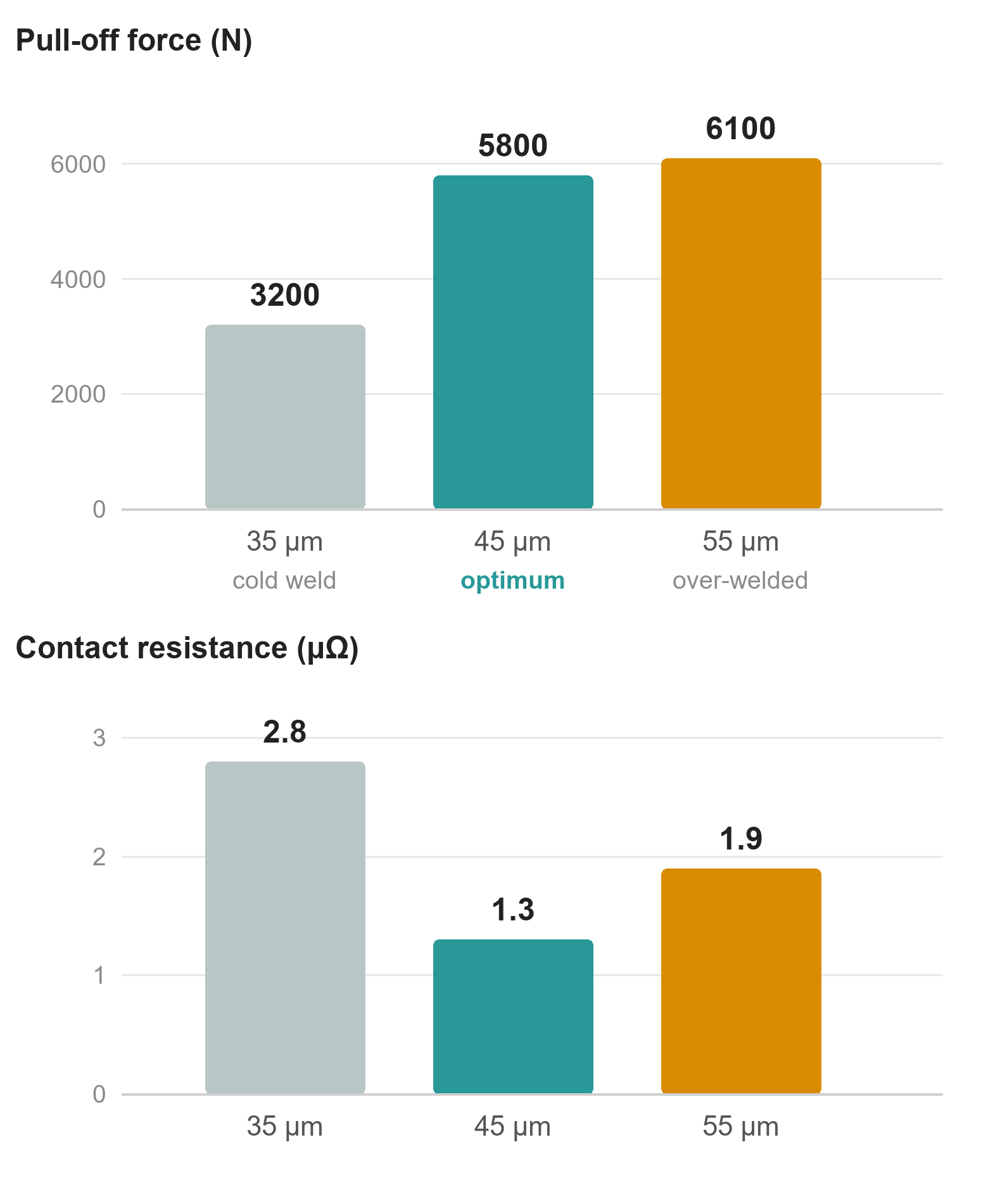
On a 70 mm² copper-to-aluminium splice, one parameter decides whether the joint holds: amplitude. During customer commissioning we fixed pressure and frequency, changed only the amplitude, and measured both pull-off force and contact resistance. The window turns out to be narrow — and the setting that looks strongest is not the best one.
The measured data
| Amplitude | Pull-off force | vs 45 μm | Contact resistance | vs 45 μm | Assessment |
|---|---|---|---|---|---|
| 35 μm | 3200 N | −45% | 2.8 μΩ | +115% | Cold weld (under-welded) |
| 45 μm | 5800 N | — | 1.3 μΩ | — | Optimum window |
| 55 μm | 6100 N | +5% | 1.9 μΩ | +46% | Over-welded |
Test conditions
- Joint: 70 mm² copper-to-aluminium splice, production tooling
- Varied: amplitude only — 35, 45 and 55 μm
- Held constant: clamping pressure, ultrasonic frequency, sonotrode, material lot
- Measured: pull-off (tensile) force, and contact resistance across the joint
- Cross-check: the same pattern reproduced on 120 mm² harnesses
Why 45 μm sits in the middle
At 35 μm the interface never gets enough relative motion: the oxide layer is only partly broken and the bonded area stays small. Force comes out low and resistance high — a cold weld, even though the machine reports a completed cycle.
At 55 μm the joint is already fully consolidated. Additional amplitude adds only 5% force while resistance climbs 46%. In our interpretation the interface is being over-worked: strands thin and work-harden, contact area is lost rather than gained, and the extra energy buys nothing.
45 μm is where both curves are still on the good side. That is what a process window means: not a single best number, but the range in which two criteria hold at the same time.
Why you need both numbers
- Force alone saturates. 6100 N looks like the strongest joint in the table — it is also the only over-welded one.
- Resistance alone cannot tell you whether the joint will survive vibration and thermal cycling.
- Treat them as one combined constraint: minimum pull-off force AND maximum contact resistance. That is also how we recommend building a DOE.
Where the window moves
- Larger sections: the pattern reproduces at 120 mm², with the optimum in the same region.
- Smaller sections: below 35 mm² it does not apply. Thin sections dissipate heat faster and need higher amplitude to reach the same bond quality.
- Material and plating: a new wire lot, a different plating thickness or a new sonotrode shifts the window. Re-bracket it instead of reusing a number.
- Machine and tooling: horn wear changes the amplitude actually delivered to the workpiece, even when the generator setting is unchanged.
How to use it on the line
- Start at 45 μm for 70 mm² Cu–Al.
- Bracket with 35 and 55 μm on your own material to confirm you are on the plateau, not on the edge.
- Accept a setting only if it passes both your force target and your resistance target.
- Re-run the bracket when the wire lot, plating, sonotrode or horn changes.
Scope and limitations
This is one commissioning series — three working points, one material lot, one machine — not a full DOE matrix. It shows where the window sits and how it behaves; it is not a guaranteed specification. Confirm it with your own design of experiments and Cp/Cpk before fixing production parameters.
Cite this data
Download the raw data:
CSV (3 rows, 4 columns) ·
chart as PNG ·
chart as SVG
Files carry English labels; the numbers are language-independent.